Detection system for a miniature MEMS X-ray source
- Faculty of Electronics, Photonics and Microsystems, Wrocław University of Science and Technology ul. Janiszewskiego 11/17, 50-372 Wrocław, Poland
Article Info
Received 28 Feb. 2023
Received in revised form 30 Jun. 2023
Accepted 07 Jul. 2023
Available on-line 30 Aug. 2023
Keywords: X-rays; luminophore; scintillator; detection system.
Abstract
The article presents the results of experiments on a detection system used for detecting signals from a miniature, low-energy micro-electro-mechanical system (MEMS) X-ray source. The authors propose to use a detection based on luminescence phenomena occurring in luminophore and scintillators to record the visual signal on a CMOS/CCD detector. The main part of the article is a review of various materials of scintillators and luminophores which would be adequate to convert low-energy X-ray radiation (E < 25 keV – it is a range not typical for conventional X-ray systems) to visible light. Measurements obtained for different energies, exposure times, and different targets have been presented and analysed.
Introduction
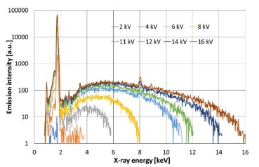
The micro-electro-mechanical system (MEMS) X-ray source being developed by the authors contains four electrodes: a cathode with a tip coated with carbon nanotubes, an extraction gate, a focusing electrode, and a target. In addition, to ensure a high and stable vacuum in the structure, an ion-sorption pump will be integrated with it. The source operates in a transmission mode, the electron beam is focused onto a silicon target, and the resulting X-rays leave the source only through a small membrane made in its centre. The radiation resulting from the interaction of the electron beam with the silicon target has a spectrum consisting of a characteristic peak with an energy of about 1.71 keV and a wide-band bremsstrahlung radiation (Fig. 1).
The source in its concept allows for the generation of a point beam of X-rays. The nature (quality, shape, etc.) of a generated beam is affected by many factors which will be optimized during the research. However, to do so, a proper detection system must be chosen which will be used to characterise the emitted beam. There are many X-ray detection systems and elements available on the market and described in the literature [1], both passive [2–5] and active [6–9]. All of them have their advantages and disadvantages. To characterise the miniature X-ray source, the most important features should have been the ability to make fast, repeatable and reliable measurement which will provide information on the intensity and spatial distribution of the beam. Moreover, due to small dimensions of the source, a reasonable solution to detect its signals is the use of small detection elements that can be placed near the source. Taking all these factors into account, the authors have decided to compose a system of a CCD/CMOS matrix and proper scintillators or luminophores that convert the X-rays to visible light.
The choice of matrix is relatively easy, it should ensure good quality and resolution, and most importantly, it should be possible to adjust all the desired acquisition parameters (most of X-ray matrix detectors do not allow to set any parameters). The choice of the proper scintillator or luminophore, adequate for the low-energy radiation, is a more complex problem and this aspect is deeply investigated within this research.
The operation of a luminophore is based on the emission of light waves as a result of excitation of the luminescent material with a factor other than that causing only the emission of thermal radiation [10]. Lumines- cence phenomena can be directly used for a detection of ionizing radiation, for example, in detectors using X-ray luminescence or radioluminescence where the generation of visible light is caused by the absorption of ionizing radiation [10].
Scintillators are elements that, under the influence of ionizing radiation, emit electromagnetic radiation with a much longer wavelength: in the ultraviolet, visible light, or infrared range. The mechanism of operation of scintillators is also based on the phenomenon of luminescence. The passage of the molecule through the scintillation material causes the ionisation process which results in the excitation of its molecules and atoms and the emission of light pulses. However, only a part of the incoming radiation energy is converted into the scintillation, the rest is converted into thermal energy.
There are three basic mechanisms of electromagnetic interactions caused by X-ray or γ radiation in the scintillator: photoabsorption, Compton scattering, and production of electron-positron pairs [4]. In the case of using a scintillator to detect signals from the miniature X-ray source, in the low-energy range the dominant process is photoabsorption. This process consists in the transfer of energy between an interacting photon and an electron from one of electron shells of the absorber atom. This produces a photoelectron which is ejected with a kinetic energy equal to the energy of the incident photon minus the binding energy of the electron in its shell. This is followed by reorganisation of the electron cloud to fill the electron gaps, resulting in the emission of Auger electrons. The highest probability of this process occurs when the energy of the initiating photon is comparable to the kinetic energy of the electron in one of the absorber atom shells [10].
The research problem in this work is to review and select elements of a detection system that allows the measurement of signals coming from a miniature MEMS X-ray source which is currently under development [11, 12]. This source will be fabricated of silicon and glass as a few cubic cm in size, and will allow generating soft X-rays with energy up to 25 keV (power < 2.5 W). X-ray detection components and systems available on the market are usually designed to detect high-energy radiation. In the case of elements and detection systems designed for low energy, such as those generated by the developed source, they are poorly available and often insufficiently described and classified. For this reason, tests and analysis of elements capable of detecting low-energy X-rays that are suitable for integration into the developed X-ray source have been carried out.
Project of the measurement system
The analysis of the detector elements for the miniature X-ray source was carried out using X-rays generated by exposing the silicon membrane to a focused beam of electrons generated in the scanning electron microscope (SEM) (Fig. 2).
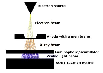
The electron beam had a well-defined spot (50 nm) and a very stable, but small emission current of 1 nA. In the final device, much higher current is planned (10–100 µA) that should allow to obtain much higher intensity of the emitted X-ray radiation. However, in the current design stage, it was impossible to ensure sufficient level of the emission stability which would not allow for repeatability of measurements. The use of SEM as a source of electrons allows tests using a strictly defined and stable electron beam which ensures the repeatability of measurement conditions.
The X-ray beam generated in the silicon membrane illuminated the examined scintillator/luminophore, and it was converted to a visible signal, recorded later by the CMOS matrix of Sony Alpha ILCE 7R photographic camera. The use of this camera to detect the resulting visible light allowed easy manipulation of acquisition parameters, like time and sensitivity. Pictures could be directly observed on a computer screen. Furthermore, the selected camera was characterised by high sensitivity with a maximum ISO of 25 600, and a full frame matrix of 35.9 mm × 24 mm (36.8 MPix) which ensures good quality images.
The most effort was put into selection of a proper material that converts X-rays into visible light. There are numerous types of luminophores and X-ray scintillators available on the market, supplied by different companies, with different form and intended for different applications. In order to choose the best one for the developed miniature X-ray source, a wide group of them have been collected and examined. All of them are listed in Table 1. The selection of the most suitable material was made based on radiation energy to which it reacts, time of luminescence decay, and available form. These elements should have the shortest possible luminescence decay time to enable potential recording of X-ray films and they should react to radiation similar to that generated by the X-ray source (see Fig. 1). The form of these elements should enable their easy integration with the rest of the X-ray source.
Table 1.
Parameters of the selected luminophore and scintillator [13, 14].
Luminophore, scintillator |
Max. spectral intensity [nm] |
Time decay [µs] |
Type/form |
Gd2O2S:Eu |
627 (red) |
850 |
Powder luminophore |
Gd2O2S:Pr |
513 (green) |
7 |
Powder luminophore |
Gd2O2S:Tb |
545 (green) |
1500 |
Powder luminophore |
luminophore from LRF_OSRAM (Ge) |
(red) |
no data |
Powder luminophore |
luminophore from LRF_POLAM (Ge) |
(red) |
no data |
Powder luminophore |
(Zn, Cd)S:Ag |
555 (red) |
1–100 |
Powder luminophore |
Y202S:Tb |
545 (blue) |
1500 |
Powder luminophore |
ZnS:Ag |
455 (blue) |
80 |
Powder luminophore |
Hamamatsu FOS J6679 [Csl (Tl)] fibre optic scintillator |
(green-red) |
0.23 |
Fibre optic scintillator |
Stintacor – luminescent film luminor ultra 5+ |
(green) |
no data |
Luminescent foil |
Photoluminescent foil from a fluorescent board (SrAl2O4:Eu:Dy) |
520 (green) |
60 min to - luminance of 35 mcd/m2 |
Luminescent foil |
Hamamatsu J8734-y020 [Csl (Tl)] |
(green-red) |
0.23 |
Scintillator |
Performance analysis of the selected luminophore
The images obtained using various types of luminophore/scintillators were analysed by plotting the intensity values of the cross-sections of these images. Since different materials gave different colour of light signal, first all images were converted into greyscale. The greyscale is expressed as a percentage where 0% is a black pixel, 100% is a white pixel, and the middle values are shades of grey. In this case, the value on the greyscale is a representation of the amount of light reaching the camera matrix, i.e., the intensity of its illumination.
Due to the point nature of the X-ray source used for measurements, the luminous intensity has a normal distribution, it is the highest in the centre and drops at the edges of the screen (Fig. 3). One can observe that the curve is quite noisy. Noise is visible in the form of grains in the recorded images. The graininess of the resulting image is probably related to the quantum noise of the photons reaching the sensor and to some extent to the high ISO value of the camera sensor (ISO = 25 600).

Examples of X-ray images created with the use of different materials and the maximum greyscale values are shown in Table 2. The noisy nature of the signal causes that the standard deviation of all results is ~ 1.3%. All measurements were taken for an acceleration voltage of 18 kV and acquired in 10 s. The time could be significantly reduced, if the emission current was higher since the relation here is proportional.
Table 2.
Summary of the X-ray images of the spot obtained for the exposure time of 10 s and
the electron beam voltage of 18 kV (silicon membrane with a thickness of 15 μm).

The best luminous intensity was obtained for the SrAl2O4:Eu:Dy luminophore which would potentially give the best results when taking X-ray images in the analysed energy range. However, it turned out to be useless because of the long luminescence decay time which would require a long break before the next measurement. Additionally, this luminophore became saturated and emitted light when exposed to visible light which further reduced its usefulness.
The rest of examined materials can be divided into three groups. The worst intensities of a signal, below 10%, were characteristic for the germanium luminophore of the mercury fluorescent lamp (MFL, in Polish – LFR); their intensity values were at the noise level. The luminophores Y2O2S:Tb, ZnS:Ag, Gd2O2S:Eu, Gd2O2S:Pr, and the fibre optic scintillator FOS J6679 [Csl(Tl)] turned out to be better with a maximum intensity between 20% and 40%. The best intensity, above 40%, was found for the luminophore Gd2O2S:Tb, (Zn, Cd)S:Ag, SrAl2O4:Eu:Dy, the Stintacor luminor ultra 5+ luminescent film, and the J8734-y020 scintillator [Csl (Tl)].
Apart from the luminous intensity, an important parameter is the resolution of the detection element. In the case of a fibre optic scintillator, its resolution is limited by the diameter and the number of fibres which, in this case, are 50 million in a 23.5 mm diameter disk, but this solution is devoid of scattering effects within the material. In the case of other elements, the resolution depends on the grain size of scintillator or luminophore material (for (Zn, Cd)S:Ag from ~ 5 to ~ 10 µm), and thickness of the layer.
The luminophore (Zn, Cd)S:Ag showed the greatest usefulness in the measurement of signals from the analysed source, both because of the second highest luminous intensity and short luminescence decay time. In addition, due to its availability in the form of a powder, this luminophore enabled easy integration with the elements of the X-ray source because of the ease of applying it to surfaces with an extensive shape. This may result in expanding the device future applications [15, 16].
Performance analysis of the selected luminophore
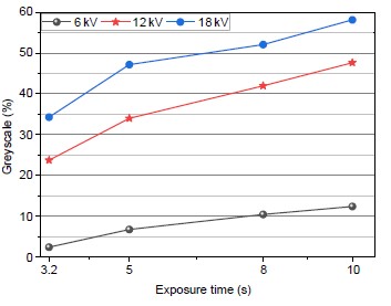
The selected luminophore (Zn, Cd)S:Ag was subjected to further examination to answer how different parameters affect the optical signal. It was noticed that the change in the intensity of the images was linear, as expected, in the function of the exposure time but not linear in the function of the electron beam energy. This luminophore showed low intensity at low energies (6 kV), even for long exposure times (Fig. 4). The energy had to be greater than ~ 10 keV to obtain high signals. In that case, even shorter acquisition times were possible to apply.
The images obtained on the CMOS matrix for different energies were collected in Table 3. For lower voltages, the image noise level increases in comparison to the useful signal and the intensity of the registered spot is small. Visually, at a voltage lower than 6 kV, the image of the spot is almost invisible. This is probably because X-ray radiation is in the range of energies for which this luminophore has a low conversion efficiency. However, an increase in the electron emission current may improve the X-ray emission and, as a result, improve the obtained image. The luminous intensity increases with increasing accelerating voltage, but the growth rate begins to decrease above an energy of 8 kV (Fig. 5).
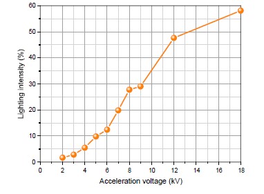
Table 3.
List of X-ray images of a spot obtained for an exposure time of 10 s and different
voltages (silicon membrane with a thickness of 15 μm).

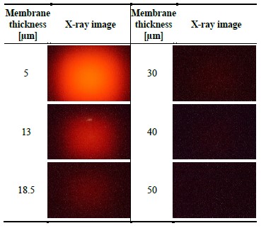
An important issue in the detection of signals from the developed X-ray source is to determine the effect of thickness of silicon membranes on the intensity of the luminophore glow. The measurements showed an increase in the luminous intensity with a decrease in the thickness of the membrane (Table 4, Fig. 6). This is due to a smaller attenuation of the X-rays in the target material. At the same time, further reduction of the membrane thickness would be unfavourable due to the risk of electrons passing through it which also causes luminescence which would falsify the X-ray measurement. Furthermore, it is technologically more difficult and generates the risk of a rapid mechanical damage. The way to increase the intensity of the X-ray radiation, without reducing the thickness of the membrane, is to deposit a thin layer of other materials on it, which would generate intensive characteristic radiation peaks [17].
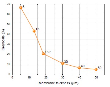
Table 4.
List of X-ray images of a spot obtained for an exposure time of 10 s and an accelerating
voltage of an electron beam of 18 kV for different membrane thicknesses.
Conclusions
The article gave an overview on how different materials react to X-ray radiation and which of them can be applied to characterise a miniature X-ray source. In most cases, the tested luminophores and scintillators worked well for the detection of soft X-rays. Particularly useful turned out to be the luminophore (Zn, Cd)S:Ag which was characterised by short luminescence decay time and high luminous intensity, even in the case of low radiation energies. The convenient form of the (Zn, Cd)S:Ag luminophore powder allows the easy application on surfaces such as glass or foil which enables easy integration with a miniature MEMS X-ray source. The designed measurement system using the (Zn, Cd)S:Ag luminophore and the CMOS matrix allows for quick testing of prototype elements of the miniature MEMS X-ray source and gives the possibility to easy measure a series of X-ray images obtained under different conditions.
Acknowledgements
The work was financed by the project 2021/41/B/ST7/01615 of Polish National Science Centre.
References
-
Urbański, P. & Grzebyk, T. Review of X-ray detection systems. Opto-Electron. Rev. 31, e146554 (2023). https://doi.org/10.24425/opelre.2023.146554
-
Knoll, G. F. Radiation Detection and Measurement. (John Wiley & Sons, 2010).
-
Cebim, M. A., Oliveira, H. H. S., Krauser, M. O. & Davolos, M. R. X-Ray-Excited Optical Luminescence in Recent Advances. in Recent Advances Complex Functional Materials (eds. Longo, E. & La Porta, F.) 177–193 (Springer International Publishing, 2017). https://doi.org/10.1007/978-3-319-53898-3_7
-
Lecoq, P. Scintillation Detectors for Charged Particles and Photons. in Particle Physics Reference Library (eds. Fabjan, C. & Schopper, H.) 45–89 (Springer International Publishing, 2020). https://doi.org/10.1007/978-3-030-35318-6_3
-
Veronese, I. et al. Radioluminescence dosimetry by scintillating fiber optics: the open challenges. Proc. SPIE 8852, 88521L (2013). https://doi.org/10.1117/12.2027041
-
Bartuś, T. Licznik Geigera-Müllera – zasada działania http://home.agh.edu.pl/~bartus/index.php?action=efekty&subaction=arduino&item=30 (Accessed Dec. 9, 2022). (in Polish)
-
REMEDI Revolution in Medical Device Portable X-Ray Digital Camera https://remedihc.com/product-portable-x-ray/ (Accessed Feb 24, 2023).
-
KETEK GmbH Silicon Drift Detectors (SDD) https://www.ketek.net/sdd/ (Accessed Feb 24, 2023).
-
https://advacam.com/camera/minipix-tpx3 (Accessed Feb 22, 2023).
-
Cebim, M. A., Oliveira, H. H. S., Krauser, M. O. & Davolos, M. R. X-Ray-Excited Optical Luminescence. in Recent Advances in Complex Functional Materials 177–193 (Springer International Publishing, 2017).
-
Grzebyk, T., Turczyk, K., Górecka-Drzazga, A. & Dziuban, J. A. Towards a MEMS Transmission Point X-Ray Source. in 34th International Vacuum Nanoelectronics Conference (IVNC) 1–2 (IEEE, 2021). https://doi.org/10.1109/IVNC52431.2021.9600697
-
Krysztof, M., Urbański, P., Grzebyk, T., Hausladen, M. & Schreiner R. MEMS X-ray Source: Electron Emitter Development. in 21st Power MEMS 248–251 (IEEE, 2022).https://doi.org/10.1109/PowerMEMS56853.2022.10007563
-
Jankowiak, P. Cathode-Ray Tube Phosphors of Interest to the Experimenter http://www.bunkerofdoom.com/tubes/crt/crt_phosphor_research.pdf (2012) (Accessed Dec. 15, 2022).
-
OSRAM Sylvania fluorescent lamps. https://web.archive.org/web/ 20110724123140/http://www.sylvania.com/BusinessProducts/MaterialsandComponents/LightingComponents/Phosphor/FluorescentLamps, (Accessed Dec. 15, 2022).
-
Cornaby, S. et al. Simultaneous XRD/XRF with low-power X-ray tubes. Proc. Adv. X-Ray Anal. 45, 34–40 (2002). https://moxtek.com/ wp-content/uploads/pdfs/simultaneous-xrdxrf-with-low-power-x-ray-tubes/SIMULTANEOUS_XRDXRF_WITH_X-RAY_TUBES.pdf
-
Górecka-Drzazga, A. Miniature X-ray sources. J. Microelectromech. Syst. 26, 295–302 (2017). https://doi.org/10.1109/JMEMS.2016.2640344
-
Urbanski, P., Bialas, M., Krysztof, M. & Grzebyk, T. Mems X-Ray Source: Electron-Radiation Conversion. in 21st Power MEMS 42– 45 (IEEE, 2022).