Photovoltaic modules with a modified ETFE foil for BIPV applications
- Institute of Metallurgy and Materials Science, Polish Academy of Sciences, ul. Reymonta 25, 30-059 Kraków, Poland
- Helioenergia Sp. z o.o., ul. Rybnicka 68, 44-238 Czerwionka-Leszczyny, Poland
Article Info
Received 18 Jul. 2023
Received in revised form 07 Sep. 2023
Accepted 13 Sep. 2023
Available on-line 21 Oct. 2023
Keywords: Photovoltaics; lightweight photovoltaic module; building integrated photovoltaics.
Abstract
This article introduces a laboratory-scale concept and research on photovoltaic (PV) modules designed for building integrated photovoltaics (BIPV) market, with enhanced architectural aesthetics and no protective glass. The proposed concept involves replacing a typical glass protective and load-bearing element of PV modules with an ethylene tetrafluoroethylene (ETFE) foil while using an aluminium sheet as a load-bearing element in the system. To further enhance the visual appeal of the solution, special modifications were proposed to the geometry of the front security foil. To confirm the feasibility of the proposed concept for mass production, critical tests were conducted on the material system and the process of modifying the surface of the ETFE foil. These tests included evaluating adhesion strength between layers, optical transmission coefficients, and electrical parameters of the developed PV modules. Additionally, the effect of the ETFE film modification on the formation of micro-cracks in solar cells was also investigated.
Introduction
Generic, commercially available photovoltaic (PV) modules have achieved a significant level of technological advancement. The conversion efficiency of the best modules on the market reaches 22.8% [1] for modules built using cells with dimensions of 182 × 91 mm2 and 24.4% for the most efficient module constructed with 108 cells with dimensions of 156 × 78 mm2 [2–4]. They have specific shape, dimensions, and tempered protective glass. They are also relatively heavy. A typical weight of the PV module typically falls within the range from 10 to 12 kg per square meter [5]. Such PV modules are used to build small PV installations, as well as large PV power plants [4]. Another heavily developed direction in photovoltaics are solutions and modules referred to as building integrated photovoltaics (BIPV) [6–7]. Generic PV modules are used in this type of application in the first place. However, the abovementioned features make the integration of such modules with existing buildings troublesome and not very aesthetic.
The solution is to use unusual PV modules with uncommon shapes, without glass and, thus made of different materials [8]. Replacing glass with other material is challenging as thermomechanical stability is to be studied and verified. Polymethyl methacrylate (PMMA) and multilayer, polymeric films are proposed as front material [9–10]. Alternative core materials are proposed and investigated [11–16]. One of concepts that can find its application in BIPV is presented and researched in this article.
Module construction concept
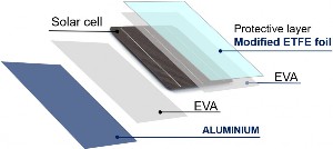
The proposed idea may act as a foundation for new BIPV products in the future. The key change in relation to the generic module is the replacement of glass with ethylene tetrafluoroethylene (ETFE) foil and modification of the foil surface. The purpose of such modification was to produce a module with unusual aesthetics and architectural attractiveness. PV modules for BIPV applications are normally based on glass, since this is the material commonly used for facades. Roofing or facade coverings based on steel and aluminium sheet may be a novelty. Due to the weight and durability of the PV module, aluminium based systems were tested.
The key problem, and at the same time the subject of the conducted research, is the development of a lamination process that will not lead to damage to any of the elements of the proposed PV module and will ensure proper protection of the solar cells against the influence of external conditions. Optical parameters are important as well, since they determine the final conversion efficiency achieved by the cells. The proposed setup will use films that exhibit a high transmittance coefficient within the solar cell operational range. For ETFE, this coefficient reaches 93%, and for ethylene-vinyl acetate (EVA) films, it is not less than 92%. The arrangement of materials proposed for the lamination tests is shown in Fig. 1. Aluminium sheet serves as the base material, while ETFE foil acts as a protective layer for the cells. The thicknesses of individual layers of materials used during the tests were as follows: ETFE: 0.1 mm, EVA front: 0.9 mm, EVA back: 0.45 mm, aluminium: 0.8 mm.
PV modules with ETFE foil as a protective layer can be found on the market [5, 6]. Most often, however, the substrate is a flexible layer or plate similar to those used in printed circuit board (PCB) systems. Aluminium sheet is the substrate in the proposed solution, but the most important novelty is the modified ETFE foil that protectsthe front of the PV module.
Research and measurements
The lamination process of the proposed system was conducted using the same conditions as a typical PV module. However, there were some differences, including the arrangement of materials and the use of a specific matrix to create the pattern. Plan of the experiment:
- preparation of materials for lamination and soldered PVcells,
- arrangement of materials in the layout as in Fig. 1,
- placing an additional matrix on the surface of the EVAfoil to create a pattern,
- lamination process (peak temperature – 145 °C, processtime – 15 min).
As a part of the research, the solar cells protection systems presented above were tested in order to determine:
- adhesion strength between materials – to obtaininformation on the mechanical durability of the joint between layers,
- optical transmission of the final systems – to determinethe influence of materials on the amount of radiation reaching the solar cells,
- electrical parameters of laminated cells – to obtain information on the effect of materials on the power of solar cells,
- electroluminescent (EL) response of the finished prototype – to determine whether there have been microcracks in the solar cells.
Adhesion tests of protective polymer layers were conducted at first to assess the correctness of the lamination process. Test were carried out using a peel-off stand equipped with a strain gauge-dynamometer system. The geometry of the sample during peel-off test is presented in Fig. 2(a), and the equipment used is visible in Fig. 2(b).
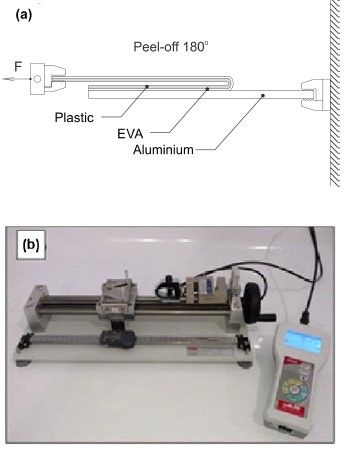
A 1 inch wide strip of material was peeled from each test sample. A strain gauge operating in the range from 1 to 500 N was used. The selection of the tested range of adhesion force was dictated by the fact that in the case of typical PV modules, the value ensuring the correct performance of the encapsulation process is assumed at the level of 150 N. Such values should also be expected when other materials are used. The research focused on two aluminium systems. The first one is made of aluminium with a raw surface (pure aluminium sheet) and the second one has a stucco-like finish of the surface (denoted as STUCCO). It is a prefabricated version of aluminium characterised by a rough surface, usually embossed at the production stage in the steelworks. The list of the adhesion strength between aluminium and EVA is included in Table 1. The list includes the systems selected for testing, but no samples were made with the ETFE protective material, as previous tests showed that the adhesion strength is higher than the destructive force of ETFE.
Table 1.
Adhesion force for tested samples.
No. |
Surface material |
Laminating polymer |
Protective material |
Lamination temperature [°C] |
Adhesion force [N] |
1 |
STUCCO Al |
EVA |
Plastic, white |
160 |
165 |
2 |
Raw Al |
EVA |
Plastic, white |
160 |
152 |
An exemplary graph of the peel-off force vs. peel-off duration for sample 2 – aluminium/EVA is shown in Fig. 3. The analysis of the obtained results shows that lamina-tion with EVA polymer to STUCCO-type aluminium gave a peel-off force of 165 N. This is a completely satisfactory result, moreover, slightly better than when using raw aluminium for which the value of 152 N was achieved.

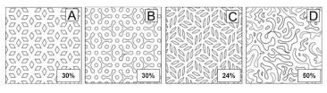
The next stage was to modify the surface of the ETFE foil by making a pattern (embossing). This process was carried out by placing a template with a pattern on the laminated system in the PV module encapsulation process. Experimental selection of the laminating membrane pressure duration was used in order to adjust the degree of pattern imprinting on the ETFE foil and the EVA foil underneath. The lamination process was carried out using the recommended EVA foil lamination time, while the pressing time of the membrane was chosen experimentally to achieve an accurate reproduction of the pattern across the entire surface of the sample. In the study, four modification variants were used, as shown in Table 2. Considering that the modification is aimed at increasing the visual attractiveness of the surface of the PV modules, the designs were given colloquial names associated with what they depict. Due to the need to conduct transmission tests, aluminium was replaced with glass.
Table 2.
Selected samples – optical tests.
Sample no. |
Modification no. |
Laminating polymer |
Protective material |
Description |
Pattern name |
Stat212 |
1 |
EVA |
Glass |
Texture 1 |
Flowers |
Stat223 |
3 |
EVA |
Glass |
Reference |
Ref. |
Stat224 |
4 |
EVA |
Glass |
Texture 4 |
Dots, spots |
Stat225 |
5 |
EVA |
Glass |
Texture 5 |
Leaves |
Stat226 |
6 |
EVA |
Glass |
Texture 6 |
Camo |
The matrix for imprinting the pattern was made of a 1 mm thick silicone mat in which the negative of the target pattern was cut out. Fig. 4 displays the matrix grid employed during the lamination process, as well as the percentage of the surface area covered by the pattern (relative to the entire surface).
The next stage was optical research which was carried out using a Lambda 950S spectrophotometer. The trans-mission was tested for systems with a reference (unmodified) ETFE foil and a foil after modification – change in surface geometry. Due to the quantum efficiency of silicon crystal-line PV cells, the measurement range was limited from 250 nm to 1500 nm.
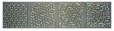
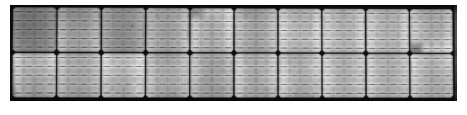
Pictures of real samples of material systems with modified ETFE foil (on which the described patterns can be seen) are shown in Fig. 5.
The next stage was optical research which was carried out using a Lambda 950S spectrophotometer. The trans-mission was tested for systems with a reference (unmodified) ETFE foil and a foil after modification – change in surface geometry. Due to the quantum efficiency of silicon crystalline PV cells, the measurement range was limited from 250 nm to 1500 nm.
The obtained results show that the transmission for all samples is at a similar level. For wavelengths above 1000 nm, characteristic curves of the EVA polymer are visible around 1200 nm and 1400 nm. Depending on the modification of the ETFE foil surface, slight differences are also visible for individual patterns (Fig. 6: visible at the enlargement for the range from 500 to 750 nm).
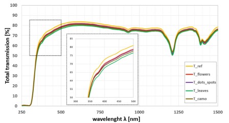
The highest transmission is shown by the reference sample and the lowest by the sample with the pattern marked “leaves”. This is mainly due to the thickness of the EVA polymer which is the smallest for flat foil and the largest for the “leaves” pattern. Hence, the conclusion that the decrease in transmission results from the greater absorption of the EVA layer. Differences in the thickness of the EVA foil result from the use of the pattern on the surface of the ETFE foil. The thickness of the ETFE/EVA layer for the reference sample was 1.8 mm and the maximum thickness of the same layer for the sample with the pattern was 2.3 mm.
For all the material systems tested and described above, samples of PV minimodules were prepared in order to assess the impact of the material arrangement system, and in particular the modification of the ETFE foil, on the electrical parameters of the solar cells. Commercial silicon bi-facial cells with dimensions of 182 × 182 mm2 were selected for the study. Cells of this type were chosen as they are the most popular on the market (with over 60% share). As indicated by ITRPV forecasts, by 2033, 90% of produced cells will be of the bi-facial type [17]. Each cell was cut into two identical pieces. The first piece was used to determine the electrical parameters of the cell without additional protective layers (marked as raw), the second was laminated in the glass-EVA-cell-EVA-ETFE foil system (marked as lam). The test results for selected minimodules are shown in Tables 3 to 7.
Table 3.
Measurement results of electrical parameters for the cell and the PV module ref. at Table 2 as 1.
|
Isc[mA] |
Voc[mV] |
Im[mA] |
Vm[mV] |
Pm[mW] |
Eff. [%] |
1 raw |
6369.7 |
670.2 |
6073.3 |
570.2 |
3462.8 |
20.97 |
1 lam |
6308.4 |
684.9 |
5999.5 |
583.8 |
3502.6 |
21.21 |
CHANGE [%] |
−0.96 |
2.19 |
−1.21 |
2.40 |
1.15 |
1.18 |
Table 4.
Measurement results of electrical parameters for the cell and the PV module ref. at Table 2 as 3.
|
Isc[mA] |
Voc [mV] |
Im[mA] |
Vm [mV] |
Pm[mW] |
Eff. [%] |
3 raw |
6331.7 |
684.0 |
6004.1 |
583.4 |
3502.6 |
21.21 |
3 lam |
6332.4 |
682.1 |
5993.1 |
583.6 |
3497.4 |
21.18 |
CHANGE [%] |
0.01 |
−0.27 |
−0.18 |
0.04 |
−0.15 |
−0.14 |
Table 5.
Measurement results of electrical parameters for the cell and the PV module ref. at Table 2 as 4.
|
Isc[mA] |
Voc[mV] |
Im[mA] |
Vm[mV] |
Pm[mW] |
Eff. [%] |
4 raw |
6328.4 |
673.9 |
6008.2 |
571.5 |
3433.5 |
20.79 |
4 lam |
6250.5 |
684.3 |
5950.5 |
584.0 |
3474.8 |
21.04 |
CHANGE [%] |
−1.23 |
1.54 |
−0.96 |
2.19 |
1.20 |
1.20 |
Table 6.
Measurement results of electrical parameters for the cell and the PV module ref. at Table 2 as 5.
|
Isc[mA] |
Voc[mV] |
Im[mA] |
Vm[mV] |
Pm[mW] |
Eff. [%] |
5 raw |
6350.3 |
670.9 |
6042.6 |
570.8 |
3449.4 |
20.89 |
5 lam |
6250.8 |
683.1 |
5972.2 |
583.8 |
3486.4 |
21.11 |
CHANGE [%] |
−1.57 |
1.82 |
−1.17 |
2.27 |
1.07 |
1.07 |
Table 7.
Measurement results of electrical parameters for the cell and the PV module 6 camo.
|
Isc[mA] |
Voc[mV] |
Im[mA] |
Vm[mV] |
Pm[mW] |
Eff. [%] |
6 raw |
6383.2 |
661.6 |
6034.6 |
561.7 |
3389.3 |
20.52 |
6 lam |
6346.5 |
678.9 |
6032.4 |
578.2 |
3487.7 |
21.12 |
CHANGE [%] |
−0.57 |
2.62 |
−0.04 |
2.94 |
2.90 |
2.89 |
The materials used for lamination and their arrange-ment in the PV module affect its final electrical parameters. Therefore, the change in short-circuit current intensity should be analysed first. It is linearly dependent on the amount of radiation energy incident on the cell surface. The obtained results show that in the case of the ETFE foil without additional modification, there is no change in this parameter. This is related to the adjustment of the optical parameters of the EVA layer to the anti-reflection layer on the cell. In the case of all modified ETFE foils, the short-circuit current decreases, but it is the smallest for the “camo” pattern. An interesting effect is the increase in the open-circuit voltage, also the highest for the “camo” sample. It may be related to the optical properties as bi-facial cells are used and the rear (also active) side of the cell may be responsible for the voltage increase. This effect is also observed in a standard system where bi-facial cells are employed instead of mono-facial PV cells. It is caused by the reflection of incident radiation in the spaces between the cells, which is then directed towards their rear active surface.
The last stage of the work was the study of the EL response for the prototype PV module made of aluminium and modified ETFE foil. The result in the form of a photo of the EL module in the described material arrangement is shown in Fig. 7.
The study showed that for the properly selected parameters of the lamination process and the proposed material arrangement system, it is possible to make a PV module in which no solar cells micro-cracks occurred despite the use of a silicone mat to modify the surface of the ETFE foil.
Conclusions
For the proposed different materials arrangement system that can be used in BIPV, several tests were performed. Adhesion tests have shown that it is possible to obtain adhesion above 150 N for samples on STUCCO-type aluminium and raw aluminium for EVA polymer. Never-theless, it is worth emphasizing that, depending on which EVA foil is used, control tests of this process should always be carried out.
Optical tests have shown that in the case of using the ETFE foil, a small loss of power of the PV cells laminated under the foil should be considered because the transmission in the short wave range from 250 to 1500 nm is lower than for typical glass used in photovoltaics. The tests of the electrical parameters of the cells laminated in the tested systems showed (similarly to the optical tests) that a thicker layer of EVA is responsible for a greater absorption of radiation and, thus, contributes to a decrease in the cell current. An interesting effect is the increase in the cell voltage (of the bi-facial type) which is probably related to the optical properties of the arrangement system for bi-facial cells.
The EL study of the prototype PV module showed that the arrangement of materials and the parameters of the lamination process can be selected in such way that no damage to the cells occurs despite the use of a matrix for modifying the ETFE film.
Summing up, the research showed that it is possible to laminate systems with unusual materials, including STUCCO aluminium sheet and modified ETFE foil, while maintaining proper adhesion and no micro-cracks in PV cells. The unusual modification of the surface significantly increases the aesthetics of such solution and may be interesting for the BIPV application area.
Acknowledgements
This research was funded by IMMS PAS as a statutory work. The transmission measurements were performed in the Accredited Testing Laboratories at the IMMS PAS (ILAC-MRA).
References
-
Hutchins, M. Longi Launches All New Back Contact Module, Promising 22.8% Efficiency. PV Magazine (2022). https://www.pv- magazine.com/2022/11/02/longi-launches-all-new-back-contact-module-promising-22-8-efficiency/
-
Green M. A. et al. Solar cell efficiency tables (Version 61). Prog. Photovolt.: Res. Appl. 31, 1–14 (2022). https://doi.org/10.1002/pip.3646
-
Yoshikawa, K. et al. Silicon heterojunctionsolar cell with inter- digitated back contacts for a photoconversion efficiency over 26%. Nat. Energy 2, 17032 (2017). https://doi.org/10.1038/nenergy.2017.32
-
New Energy and Industrial Technology Development Organization Kaneka Corporation. World’s Highest Conversion Efficiency of 24.37% Achieved in a Crystalline Silicon Solar Cell Module – Represents Significant Progress toward Power Generation Cost Targets. News Release. (2016). https://www.kaneka.co.jp/topics/uploads/2017/06/1479120629_101.pdf
-
Mik, K., Zawadzki, P., Tarłowski, J. & Bykuć, S. Assessment of prototype lightweight photovoltaic modules after over 1-year field test in Polish conditions. Renew. Energy 198, 1008–1020 (2022). https://doi.org/10.1016/j.renene.2022.08.104
-
Shukla A. K., Sudhakar, K. & Baredar, P. Recent advancement in BIPV product technologies: A review. Energy Build. 140, 188–95 (2017). https://doi.org/10.1016/j.enbuild.2017.02.015
-
Jelle, B. P., Breivik, C. & Drolsum Røkenes, H. Building integrated photovoltaic products: A state-of-the-art review and future research opportunities. Sol. Energy Mater. Sol. Cells 100, 69–96 (2012). https://doi.org/10.1016/j.solmat.2011.12.016
-
Tsai, Ch.-Yi. & Tsai, Ch-Yao. See-through, light-though, and color modules for large-area tandem amorphous/microcrystalline silicon thin-film solar modules: Technology development and practical considerations for building-integrated photovoltaic applications. Renew. Energy 145, 2637–46 (2020). https://doi.org/10.1016/j.renene.2019.08.029
-
Li, M. et al. Polymer multilayer film with excellent UV-resistance & high transmittance and its application for glass-free photovoltaic modules. Sol. Energy Mater. Sol. Cells 229, 111103 (2021). https://doi.org/10.1016/j.solmat.2021.111103
-
Drabczyk, K. et al. Study of lamination quality of solar modules with PMMA front layer. Microelectron. Int. 34, 100–103 (2019). https://doi.org/10.1108/MI-12-2018-0087
-
Sobik, P. et al. The impact of ribbon treatment on the interconnec- tion of solar cells within a glass free PV module. Microelectron. Int. 36, 95–99 (2019). https://doi.org/10.1108/MI-11-2018-0076
-
Martins, A. C., Chapuis, V., Virtuani, A. & Ballif, C. Light and durable: Composite structures for building-integrated photovoltaic modules. Prog. Photovolt. 26, 718–29 (2018). https://doi.org/10.1002/pip.3009
-
Martins, A. C., Chapuis, V., Virtuani, A. & Ballif, C. Robust glass- free lightweight photovoltaic modules with improved resistance to mechanical loads and impact. IEEE J. Photovolt. 9, 245–251 (2019). https://doi.org/10.1109/JPHOTOV.2018.2876934
-
Ballif, C., Perret-Aebi, L. E., Lufkin, S. & Rey, E. Integrated thinking for photovoltaics in buildings. Nat. Energy 3, 438–42 (2018). https://doi.org/10.1038/s41560-018-0176-2
-
Kajisa, T. et al. Novel lighter weight crystalline silicon photovoltaic module using acrylic-film as a cover sheet. Jpn. J. Appl. Phys. 53, 092302 (2014). https://doi.org/10.7567/JJAP.53.092302
-
Martins, A. C. et al. Thermomechanical stability of lightweight glass-free photovoltaic modules based on a composite substrate. Sol. Energy Mater. Sol. Cells 187, 82–90 (2018). https://doi.org/10.1016/j.solmat.2018.07.015
-
ITRPV, International Technology Roadmap for Phtovoltaic 4th ed., Berlin. (2023). www.itrpv.org