

Received 08 Jun. 2023
Received in revised form 16 Sep. 2023
Accepted 18 Sep. 2023
Available on-line 06 Dec. 2023
Keywords: Generalised frequency division multiplexing (GFDM);turbulence;pointing error;forward error correction (FEC);decision feedback equaliser (DFE).
Underwater wireless optical communication is the best alternative for many applications especially for high bandwidth data communication between underwater objects and vehicles. The implementation of coding scheme along with advanced modulation technique and equalisation methods is identified as a key research scope for enhancing the performance of the system. In this paper, the coded generalised frequency division multiplexing (GFDM) technology is employed to provide high-data rates and less out-of-band emission. The Bose-Chaudhuri-Hocquenghem (BCH) and Reed-Solomon (RS) coding schemes along with equalisation techniques namely normalised least mean square (NLMS)-based decision feedback equalisers (DFE), minimum mean square error (MMSE) and zero forcing (ZF) are utilized to reduce inter symbol interference (ISI). The bit error rate (BER) performance is evaluated in the presence of pointing error (PE) and turbulence using Monte Carlo channel modelling simulations. The results showed that RS coding with NLMS-DFE outperforms other techniques and achieves a BER of roughly 10−5 with a signal-to-noise ratio levels below 20 dB. The simulation results demonstrate that RS code with 15 total symbols per code word and 3 data symbols, i.e., RS (15, 3) and BCH code with 31 total symbols in a code word and 6 data symbols, i.e., BCH (31, 6) provided the best error performance among other coding schemes employed. It is inferred that RS (15, 3) coded 2 × 2 multiple input multiple output systems with NLMS-DFE achieved a BER value of 1.1925 × 10⁻⁵ at 11 dB which is 16 dB less than uncoded system. Thus, the coded GFDM improves overall BER performance and has the potential to provide higher reliability for internet of underwater things (IoUT) applications.
The most popular technology for transferring data over distances of several kilometres is the underwater acoustic communication (UAC) [1]. Due to a limited bandwidth in the order of kHz and a reduced carrier frequency of 1 MHz, UAC has low-data speed and throughput [2]. It is evident that UAC has the following characteristics: less transmission rate of about 1500 m/s, high multipath loss, expensive antenna requirements, sensitivity to ambient noise and echoing [3].
Since radio frequency (RF) signals in underwater communication experience significant attenuation or signal loss when traveling through water, the degree of att0enuation depends on factors such as frequency, distance, water composition, and other physical properties. As a result, the range of RF communication in underwater is typically limited compared to in-air applications [4].
However, the underwater wireless optical communication (UWOC) technology offers a significantly higher bandwidth around MHz for the maximum distances of 10–100 m and offers less power consumption, higher-data rates and low latency [5–8]. Since it has less attenuation than other ranges, the blue-green region (445 –570 nm) is better suited for UWOC systems [9, 10]. Apparently, one of the main factors restricting such communication systems is due to absorption and scattering processes in the underwater environment [11]. Since the propagation of light is very crucial in the underwater world, channel modelling helps analyse the effects of factors such as absorption, scattering, beam spreading, and beam wandering. It provides insights into the signal degradation mechanisms, allowing for the optimisation of system parameters [12].
The presence of turbulence in underwater (UW) channels leads to fluctuating water refractive index gradients, resulting in time-varying fading and scintillation effects. Additionally, pointing errors (PEs), caused by mechanical misalignments or movements of the transmitter and receiver, can introduce misalignment losses and misdirected laser beams. These factors impose significant challenges on achieving reliable communication over underwater optical channels.
Underwater optical communication systems have emerged as a promising technology for high-speed data transmission in aquatic environments. These systems utilize laser beams to carry information through the water, offering the potential for substantial bandwidth and data rates. However, underwater optical channels are subject to various impairments, including turbulence-induced fading and PEs which may severely worsen the performance of a channel link.
To reduce the hostile effects of underwater PEs and turbulence, advanced modulation and equalisation techniques are required. Generalised frequency division multiplexing (GFDM) has better substantial attention as a promising modulation scheme owing to its capability to handle frequency-selective channels efficiently. To limit the out-of-band (OOB) radiation, GFDM uses pulse-shaping filters [13]. When compared to the orthogonal frequency division multiplexing (OFDM), GFDM approach has a very small cyclic prefix (CP) applied to it. As a result, the GFDM system overall spectral efficiency is increased. GFDM ability to deliver higher-data rates with reduced latency is one of its main advantages.
Another main challenge in UWOC requires advance-ments in optical transceiver technology, signal processing techniques, modulation, and coding schemes. Hence, there is a need to address all above issues for achieving higher spectral efficiency, reduced bit error rate (BER) to enhance the overall system performance in real time applications. The use of a coding scheme with advanced modulation approach and equalisation techniques over UWOC system, to our knowledge, is very limited in the current literature.
This paper focuses on investigating the BER perfor-mance of a coded GFDM based on UWOC system by employing different equalisers at the receiver. By lever-aging the combination of GFDM modulation, channel coding and equalisation, this research aims to provide insights into the system performance and its resilience to turbulence and PEs.
In this work, a comprehensive performance evaluation of GFDM system is conducted with Reed-Solomon (RS) and Bose-Chaudhuri-Hocquenghem (BCH) channel coding schemes under various turbulence scenarios and PE conditions. The performance metrics primarily focus on the BER which represents the accuracy of the received symbols. Accurate channel estimation is also necessary to offer additional signal processing to mitigate the channel effects at the receiver. Henceforth, various equalisation methods are employed to improve the overall performance of the system for reliable communication.
The contributions of this research can help in understanding the trade-offs between different modulation, coding, and equalisation techniques for underwater optical communications. The simulation results provide valuable insights into the design and optimisation of robust and efficient communication systems for underwater applications. Additionally, these findings can facilitate the development of strategies for mitigating PEs and turbulence-induced fading and then ultimately improving the reliability of UWOC system.
The main highlights of the proposed work are summarised as:
coded GFDM technique is adopted to provide enhanced interference rejection capabilities which lead to significant improvement in performance;
impact of underwater turbulence and PE in UW channel is analysed;
various equalisation algorithms have been investigated to mitigate the inter-symbol interference and improve the BER performance of underwater optical communi-cation systems.
The remaining work is represented as: section 2 explains the related works of the proposed performance in UWOC; section 3 describes the system and channel model; section 4 explains the channel encoding and decoding schemes; section 5 explains the channel modelling; section 6 discusses the equalisation techniques adopted in this work; section 7 specifically discusses the results of the GFDM-based UWOC system, and section 8 contains the conclusions.
There has been a great deal of research done to characterise the UWOC system. The Monte Carlo (MC) approach is a well-known method for UW channel simula-tion. To calculate the channel parameters, it is necessary to monitor the photons propagated through the medium [14]. Underwater visible light communication (UVLC) system performance will suffer from dispersion, absorption, turbulence effects, and scattering. According to Refs. 15 and 16, the theoretical BER for multiple input multiple output (MIMO) direct current-biased optical (DCO) OFDM (DCO-OFDM) system is explained based on an approximation of the weighted sum of log-normal random variables and performs well within UW channels.
For a realistic assessment of UWOC performance, detailed descriptions of turbulence-induced channels under various underwater conditions are required. The authors of Ref. 17 presented a thorough experimental viewpoint on statistical analysis of air bubble effect, turbulence, temperature gradient, and salinity of UWOC systems. The effectiveness of the UWOC system multi-aperture reception under varying channel irradiance is depicted by the exponential-generalised gamma (EGG) distribution in Ref. 18. In this study, the performance of the system was analytically evaluated using receivers combining selection and maximum ratios which outperform single-aperture-based systems using multi-aperture components.
Optical turbulence, scattering, and absorption are the main causes of attenuation. The scattering will disperse the light beam and decrease the photons captured by the receiver, thereby reducing the signal-to-noise ratio (SNR) of the overall system as optical aperture has a finite size [19]. The main factors contributing to optical turbulence include salinity, turbidity, temperature, and presence of air bubbles which also affect the functionality and durability of UWOC devices [20]. Thus, the light propagation of UWOC is ultimately affected by many parameters. Hence, a standard mathematical modelling of UW channel will be helpful for future theoretical research and experimental planning [21]. Majlesein et al. [22] demonstrated a complete model for UWOC and determined the BER performance for various water conditions over an 8 m distance by considering all distortions in optical beam using MC simulation. Blue, green, and red laser beams scintillate in variation of light intensity and weakly salinity-induced oceanic turbulence is analysed [23] under various salinity-induced turbulence strengths. Reference [24] revealed the effect of temperature gradients on BER performance of low density parity check (LDPC)-coded UWOC systems.
The scintillation index in the UW channel [25] rises with increasing temperature inhomogeneity and the non-coherent light beam is also more resistant to the turbulence impact. Various mitigation techniques for improving the overall performance in underwater turbulence were reviewed [26]. In comparison to the single input single output (SISO) system, MIMO vertical visible light communication (VLC) connection in weak turbulence improved the outage probability and performed about 6 dB better for four transceiver configurations [27]. For underwater turbulence, BER of intensity modulated binary phase shift keying (BPSK) in optical wireless communication (OWC) links [28], capacity of channel and outage probability in weak-to-strong turbulence using Malaga distribution, and BER performance of pulse position modulation (PPM)-based OWC with gamma-gamma distribution [29] were examined. Maintaining the line of sight (LOS) for a reliable underwater link is crucial because the optical beam in UOWC is quite narrow. A continuous tracking between transceivers is crucial to maintain a continuous, reliable link because of the motion created by ocean currents, underwater vehicles, and turbulent sources [30].
The use of error correction codes, such as RS and BCH codes, was essential to mitigate the effects of noise and distortion. The effectiveness of BCH codes in mitigating the impact of channel impairments was investigated. The design and optimisation of the BCH code parameters to achieve efficient error correction are experimentally analysed over turbid channel for reliability of data trans-mission in underwater environments [31]. In Ref. 32, RS codes are used to reduce the channel turbidity effects by varying the attenuation coefficients.
Multi-carrier modulation (MCM) techniques have gained significant attention in the field of underwater optical communication due to their ability to mitigate the adverse effects of multipath propagation and enhance the overall system performance. MCM techniques, such as OFDM will effectively mitigate multipath interference by dividing data into multiple subcarriers, thereby improving the system resilience to multipath fading. Also, they enable high-data rate transmission facilitating faster and more reliable communication in underwater environments.
Underwater optical channels may exhibit nonlinear effects due to high optical intensities and long propagation distances. MCM techniques can mitigate the impact of nonlinearities by employing subcarrier spacing and power allocation schemes that minimise the accumulation of nonlinear distortions. Therefore, MCM techniques enablehigh-data rate transmission, improve system robustness, and enhance channel equalisation, making them a vital component in the advancement of underwater optical communication technologies.
OFDM is a widely adopted MCM technique allowing efficient spectrum utilization, mitigating multipath inter-ference, and providing robustness against multipath fading by employing CPs and frequency-domain equalisation. However, it is sensitive to carrier frequency offset, which can arise due to imperfect synchronisation. Also, OFDM signals exhibit a high peak-to-average power ratio (PAPR), which can cause power inefficiency and lead to nonlinear distortion in optical components.
Xu et al. [33] proposed an UOWC system based on intensity modulated/direct detection (IM/DD) OFDM. The BER and optical link range were estimated using a quadrature amplitude modulation (QAM) with various orders and subcarriers for a 40 m transmission link operated in a coastal area. The experimental results indicated that, at a 2 m link distance, the net data rates were 1231.95 Mb/s for a BER of 3.28 × 10⁻³ using 32-QAM and 225.9 Mb/s at a BER of 11.54 × 10⁻³ using 16-QAM. Jamali et al. [20] proposed on-off keying (OOK) modulation with the MIMO approach for the performance study of the UOWC system. The simulation findings illustrated that spatial diversity could greatly enhance system performance. Additionally, to reduce the impact of turbulence, MIMO introduces an 8 dB performance booster by employing the 3 × 1 MISO approaches within a 25 m coastal water connection range. Huang et al. [34] examined the BER performance using the MIMO with a spatial modulation (SM) method. However, the SM requires a complete knowledge of the UW channel for data identification to achieve higher spectral efficiency than the conventional MIMO method. Amantayeva et al. [35] examined the UVLC system performance evaluation using OFDM-based 2 × 2 MIMO method in murky water. The channel gain was evaluated using the weighted double gamma function (WDGF). A ZF pre-coding approach was used by the researchers to remove multiuser interference.
Filter bank multi-carrier (FBMC) is an alternative to OFDM that provides improved spectral efficiency and has better OOB radiation suppression compared to OFDM, making it suitable for reduced ISI and better interference management. But it requires sophisticated filter designs and computationally demanding signal processing algorithms, leading to increased complexity. Similar to OFDM, it is sensitive to carrier frequency offset, which can affect performance in the presence of synchronisation errors. FBMC becomes significantly more efficient than OFDM for a limited number of subcarriers [36].
Another alternate and recent MCM scheme called GFDM is a very flexible MCM technique that can offer improved performance in terms of interference mitigation and spectral efficiency for 5G applications. It has low OOB radiation suppression and employs advanced filtering techniques and pulse-shaping to provide enhanced interference rejection capabilities [37].
Channel equalisation and adaptive optics are two cutting-edge signal processing techniques that are used to reduce interference at the receiver. A detailed assessment of an optical aquatic channel will help to choose the right system design parameters for robust and high- quality optical links [38]. Ramadan et al. [39] introduced a banded-matrix approximation-based ZF equaliser for MIMO-OFDM based on a discrete wavelet transform (DWT). The proposed scheme performs better than other schemes under channel conditions spatially. For the LED-based UWOC system, Fei et.al. [ 40] suggested sparse pruned term (SPT)-based non-linear decision feedback equalisation (NDFE), SPT-NDFE method experimentally for lower level of complexity (decreased by 63.63%) in turbid water. The proposed systems suggested channel equalisation techniques with low complexity and high performance. In Ref. 41, the step size for an equaliser is calculated and the results are compared with those of two well-known equalisers such as CP-OFDM equaliser and DFE interleave division multiple access (IDMA). By adding the attenuation loss, ambient noise, and surface loss together, the overall path loss is calculated. According to simulation results, the suggested methodology achieves a better BER of 10−2 for short-range UAC channels.
Reference 42 presents a comprehensive study on the use of MC simulations for UOWC systems. It discusses the challenges of UOWC, such as scattering, absorption, and turbulence, and explains how MC simulations can accurately model these effects. The authors provide simulation results for different UOWC scenarios, evaluating the system performance under various conditions. Qiao et al. [43] employed MC simulations to analyse the BER performance of UWOC systems. They consider factors such as channel attenuation, background noise, and optical power
GFDM is the ideal technique for overcoming the shortcomings of the existing OFDM system in terms of improved flexibility, spectrum efficiency, and low OOB emissions for the next generation of communication networks [44]. The main objective of this work is to examine the performance of the coded GFDM in UWOC systems, in which the data signals are transmitted by 𝑀 transmitters and it is received by 𝑁 apertures. With the help of different equalisers, the channel performance is analysed.

The block diagram for the continuous-time GFDM transmitter is shown in Fig. 1. The GFDM signal 𝑥(𝑡) is given as
\( \tilde{x}(t)=\sum_{n=0}^{N-1} \sum_{m=0}^{M-1} X_{n, m} g(t) e^{j \frac{2 \pi n t}{T s}} \) (1)
where 𝑋𝑛,𝑚 denotes the transmitted symbol, 𝑔(𝑡) is the transmitted filter as described in (2), 𝑇𝑠 is the symbol duration, 𝑁 represents the number of sub-carriers and 𝑀 denotes the number of sub-symbols.
\( g(t)=w(t) \cdot g\left(t-m T_s\right) \) (2)
The transmitted filter 𝑔(𝑡) is expressed by multiplying the periodic shaping pulse 𝑔(𝑡−𝑚𝑇𝑠 ) with 𝑤(𝑡), the windowing pulse of time 𝑇=𝑀𝑇𝑠.
The GFDM signal power spectral density (PSD) (by assuming raised cosine pulse-shaping) is given as
\( S_{\tilde{x}}(f)=\frac{E}{T} \sum_{n=0}^{N-1} \sum_{m=0}^{M-1}\left|G\left(f-\frac{n}{T_s}\right)\right|^2 \) (3)
where, 𝐺(𝑓) is the Fourier transform of 𝑔(𝑡) and 𝐸 denotes the mean energy of 𝑋𝑛,𝑚 .
\( G(f)=\frac{1}{T} \sum_{-\infty}^{\infty} G_T\left(\frac{i}{T}\right) W\left(f-\frac{i}{T}\right) e^{-j \frac{2 \pi m i}{M}} \) (4)
where 𝑊(𝑓) is the Fourier transform of 𝑤(𝑡).
The GFDM receiver is represented as the matched filter receiver and the expression of the received symbol mathematically is given as
\( \hat{x}_{n, m}=\int_{-\infty} \tilde{r_k}(t) g(t) e^{\frac{j 2 \pi n t}{T s} t} d t \text {, } \) (5)
where 𝑟𝑘(𝑡) represented by
\( \tilde{r}_k(t)=\int_{-\infty}^{\infty} \tilde{h}(t, \tau) \tilde{x}(t-\tau) d \tau+\tilde{n}(t) \) (6)
where denotes the impulse response of the channel and 𝑛(𝑡) denotes the additive white Gaussian noise (AWGN) with variance 𝑁0 and zero mean. Using (1) in (6), a new version of (5) is written as
\( \hat{x}_{n, m}=R_{n, m} X_{n, m}+I_{n, m}+N_{n, m} \) (7)
where the expressions of 𝑅𝑛,𝑚 , 𝑁𝑛,𝑚 and 𝑁𝑛,𝑚 are given below:
\( R_{n, m}=\int^{\infty} \int^{\infty} \tilde{h}(t, \tau) g(t-\tau) g(t) e^{-j \frac{2 \pi n_1 \tau}{T s}} d t d \tau \) (8)
\( I_{n, m}=\sum_{\substack{n_1=0 \\\left(n_1 \neq n,\right.}}^{N-1} \sum_{\substack{\left.m_1=0 \\ m_1 \neq m\right)}}^{M-1} X_{n_1, m_1} R_{n_1, m_1}(n, m) \) (9)
\( N_{n, m}=\int_{-\infty}^{\infty} \tilde{n}(t) g(t) e^{\frac{-j 2 \pi n t}{T s}} \) (10)
By considering the pulse-shaping, up-sampling, and subcarrier up-conversion in matrix notation, the transmitted signal of GFDM transmitter is modelled as [45]
\( \mathbf{X}=\mathbf{A x}, \) (11)
where 𝐀 represents the 𝑀N × 𝑀N transmitter modulation matrix [1]. Also, the implementation of a low-complexity technique of the GFDM transmitter model is evaluated in Ref. 46, where 𝑠 is modelled as
\( \mathbf{X}=\boldsymbol{\Gamma}^{\mathrm{H}} \overline{\mathbf{x}} \) (12)
where (.) H represents the Hermitian symmetry operator, 𝚪= 𝐅b𝐀H, 𝐱 = 𝐅b𝐱 and 𝐅b is the 𝑀N × 𝑀N normalised matrix of discrete Fourier transform (DFT). Finally, the vector 𝐱 on the transmitter side is appended with CP of 𝑁CP sample length to generate the transmit signal vector 𝐱 with length of 𝑀N +𝑁cp, which is added to reduce ISI.
In the receiver model, let us assume that the system has channel knowledge with perfect frequency and time syn-chronisation. The receiver structure of a GFDM signal is employed with various equalisers. To obtain the estimation results of the transmitted data from equalised and received signal 𝑦(𝑛), the operation of signal processing can be carried out at the receiver
\( \hat{x}=\mathbf{B} \cdot y \) (13)
The matrix 𝐁 can be represented by Ref. 2 as
\( \mathrm{ZF}: \mathbf{B}_{\mathrm{ZF}}=\mathbf{F}_{\mathrm{b}}^{\mathrm{H}} \mathbf{X}^{-1} \boldsymbol{\Gamma} \) (14)
\( \text { MMSE: } \mathbf{B}_{\text {MMSE }}=\left(\mathbf{F}_{\mathrm{b}}^{\mathrm{H}} \mathbf{X F}_{\mathrm{b}}+\sigma_w^2 \mathbf{I}_{M N}\right)^{-1} \mathbf{A}^{\mathrm{H}} \) (15)
where MSE is the minimum mean square error, 𝜎𝑤2 is the noise variance, and
\( \mathbf{X}=\mathbf{F}_{\mathrm{b}}\left(\mathbf{A}^{\mathrm{H}} \mathbf{A}\right) \mathbf{F}_{\mathrm{b}}^{\mathrm{H}} \)
is the 𝑀N × 𝑀N diagonal matrix.After bit streams are generated in this work, channel coding is carried out by utilizing the BCH and RS coding techniques. QAM is used throughout the symbol mapping process to lower error rates at receiver. Those mapped symbols were sent via a pulse-shaping filter like an RC filter before being used in an inverse fast Fourier transform (IFFT) operation. To counteract the impact of ISI, CP would be introduced after IFFT before power allocation. The sum of all signals transmitted powers 𝑃𝑃 is then determined. Then, the transmitted signal is represented as
\( x_1=\sum_{i=1}^N \sqrt{P_i} x_{1, i} \) (16)
\( x_2=\sum_{\mathrm{i}=1} \sqrt{P_i} x_{2, \mathrm{i}} \) (17)
where 𝑃𝑖 indicates the power allocated to each transmitter.
These two signals are converted first into analogue signals by D/A converters and then, using a 532 nm wavelength laser source (green LED), they are converted into optical signals before being transmitted through the UW channel. These signals are then captured by two avalanche photodetectors (APDs) at the receiver end which use an A/D converter to split them into two data streams. The CP is separated completely from data streams and then a demodulation process is carried out which combines fast Fourier transform (FFT) and RC-pulse de-shaping filter operation followed by equalisation adopted at the receiver. Finally, channel decoding was performed in order to recreate the original data streams after the de-multiplexing operation using QAM symbols.
The channel model of the UWOC link employing GFDM modulation is described.
The received signal at detector is given by Ref. 47
\( Y=\eta_i I \mid \sqrt{P T B}+N \) (18)
where 𝜂𝑖 is the photo detector responsivity, 𝑇 is the bit duration, 𝑁 is the sample value of AWGN with the variance 𝜎2 and zero mean, 𝐵 ∈[0,1] is the transmitted bits and 𝐼=𝐼𝑟∙𝐼PE∙𝐼𝑎, (product of fading coefficients due to turbulence, PE, and attenuation, respectively [48]).
In the underwater medium, attenuation due to a fading coefficient is always specified by Beer-Lambert’s law [1] as
\( I_a=\exp (-D C(\lambda)) \) (19)
where 𝐷 indicates the link distance and 𝐶 (𝜆) represents the wavelength-dependent attenuation coefficient (sum of absorption and scattering).
The received irradiance with turbulence is modelled by a logarithmic normal density function, which is given as
\( f\left(I_r\right)=\frac{1}{2 I_r} \frac{1}{\sqrt{2 \pi \sigma_X^2}} \exp \left(-\frac{\left(\ln \left(I_r\right)-2 \mu_X\right)^2}{8 \sigma_X^2}\right) \) (20)
where 𝜎𝑋2 and 𝜇x are the variance and mean of Gaussian random parameter 𝑋=12ln (𝐼𝑟).
Another issue due to misalignment between transmitter and receiver is called PE. This will occur mainly due to water currents, turbulence, and wave movement. The performance of the system is also impacted by PE and geometric beam spread in addition to turbulence and attenuation. When a transmitting beam travels through the atmosphere, it diverges as shown by the equation 𝑍=𝑇𝑑aL, where 𝑍 is the received beam waist, 𝑇𝑑a is the transmitter divergence angle, and 𝐿 is the propagation path length. A portion of the transmitted power gets lost if the received beam width typically exceeds the size of the lens aperture. Since the receiver aperture radius, 𝑅, and the received beam waist, 𝑍, are proportional, the 𝑍/𝑅 ratio can be calculated by appropriately changing the laser parameters.
However, errors in the targeting, acquisition, and tracking between the unmanned aerial vehicles (UAVs) and ground stations might also result in loss. Therefore, a precise generic model suggested in Ref. 2 has been considered. The attenuation resulting from the geometric spread with PE is approximated as Gaussian form in this model:
\( I_{p e} \approx A_0 \exp \left(-\frac{2 \rho^2}{w_{e q z}^2}\right) \) (21)
where 𝐴0 is the fraction of power collected without PE, 𝜌 is the PE, Wez is the equivalent beam width equal
\( \frac{z^2 \sqrt{\pi} \operatorname{erf}(\mu)}{2 \mu \exp \left(-\mu^2\right)} \)
is the error function and
\( \mu=\frac{v \pi r}{\sqrt{2} z} \)
Let the impulse response with length 𝑁ch be ℎ=[ℎ0…,ℎ 𝑁ch-1]T. The signal is propagated over UW channel and the CP is removed from the received signal which is modelled as
\( r=\mathbf{H} x+\mathbf{W} \) (22)
where ℎ is called the zero padded version of 𝐡 and H = circ{ℎ}. The vector 𝐖 ~ CN(0, 𝜎W2 𝐈mn ) represents AWGN samples along with noise variance 𝜎W2 and Imn is the identity matrix with the MN order. The individual element of 𝑟(𝑛) is represented as\( r(n)=x(n) * h(n)+w(n) \) (23)
where (∗) represents the convolution and the noise is an uncorrelated AWGN, then ℎ(𝑛)= 1.
Forward error correction (FEC) codes were used in wireless communication for the lowest SNR, and it is usually used for controlling the error while transmitting data [49]. Block codes work with symbols or bits that have a fixed length and size. Due to their simplicity and robustness in error correction, BCH and RS codes are favoured mostly for UWOC system [50]. Error-correcting codes make extensive use of finite fields, a class of complex algebraic structures. It is sometimes referred to as a Galois field (GF) because those elements would be combined to form new elements from the collection by adding, subtracting, multiplying, and dividing them.
The optical signals are mainly attenuated due to a harsh environment in UW channel. Therefore, to detect and correct errors in the medium, a suitable channel coding technique needs to be adopted. In this study, different coding schemes have been selected. The BCH codes are the bit error correcting codes over 𝑛=2𝑚−1 bit length in GF(2m). Where m is the positive real integer (𝑚≥ 3). The field elements are characterised by {0,1,𝛼,𝛼2,…,𝛼((2M)−2)} and 𝛼 is the primitive element in GF(2m) [1] The generator polynomial is usually determined by considering the least common multiple of a polynomial with elements 𝛼𝑏, 𝛼𝑏+1, 𝛼(𝑏+𝑘−2), where 𝑏≥ 1 and 𝑘=2𝑡+1 [50].
The generated polynomial is found as
\( g(x)=\operatorname{LCM}\left\{M_b(x), M_{b+1}(x), \ldots, M_{b+k-2(x)}\right\} \) (24)
where 𝑀𝑏(𝑥) denotes the minimal polynomial of 𝑏th conjugacy class [51].
The generator matrix is determined by using 𝑔(𝑥). Then the encoded BCH data is modulated using GFDM and it is transmitted through the laser diode and then, propagated through the underwater medium. Then, the received signal is passed through the receiver module, and it is demodu-lated to regenerate the original data. But the received signal may contain errors created by aquatic channel. Berlekamp Massey (decoding) algorithm is used [52] to correct the errors in the signal received at the receiver
RS codes have great burst error-correcting capabilities for improving the integrity of data transmission. It works by oversampling the generated polynomial and the step-by-step analysis of the polynomials yields the better results. The receiver can reconstruct the original polynomial until the point at which it gets the value correctly. Each root of the generator polynomial created by the RS code is a sequential element in GF [53].
Due to random errors introduced into the data stream, the transmission path could be completely blocked. This error can be corrected only via channel codes. Since the probability of error induced in the underwater data stream often occurs in UWOC system, the error-correcting capabilities of RS code is good enough [54] to enhance the integrity of transmitted data.
The generator polynomial of length (𝑛, k) over Galois Field GF(𝑞) is expressed as
\( g(x)=\left(x-\alpha^b\right)\left(x-\alpha^{b+1}\right) \ldots\left(x-\alpha^{b+k-2}\right), \quad b \geq 0 \) (25)
where 𝛼 is the primitive element of GF(𝑝𝑚), (𝑞=𝑝𝑚) ,𝑝 is the prime number and 𝑚 is the order of field extension, 𝑘=2𝑡+1 where t is the error correcting capability of symbol.
The above (25) is rewritten by substituting 𝑏= 1 and the value of 𝑘 as in Ref. 1, thus
\( g(x)=(x-\alpha)\left(x-\alpha^2\right) \ldots\left(x-\alpha^{2 t}\right) \) (26)
The code word polynomial is expressed by
\( c(x)=g(x) * s(x) \) (27)
where 𝑔(𝑥) is the generator polynomial and 𝑠(𝑥)=𝑠0+𝑠1𝑥+𝑠2𝑥2+⋯+𝑠𝑘−1𝑥(𝑘−1) is the message polynomial attained by considering 𝑘𝑘 message symbols 𝑠0,𝑠1,𝑠2,…,𝑠𝑘−1 as a polynomial.
The 𝑛 length code word in the polynomial form can be denoted as
\( c(x)=c_0+c_1 x+c_2 x^2+\cdots+s c_{n-1} x^{n-1} \) (28)
In this work, various coding schemes have been employed for correcting the errors. Each symbol of code word polynomial is transferred over the UWOC channel by a GFDM modulated laser source. In receiver, the received bits were then processed to find the error magnitude and location. Then, the Chien search algorithm and Berlekamp-Massey algorithm are used to detect and correct induced errors. The estimation of the transmitted code word is obtained by
\( \hat{c}(x)=r(x)-(x) \text { and } e(x)=x \sum_{i=0}^{n-1} e_i x^i \) (29)
where 𝑒𝑖 is the 𝑖th error magnitude and 𝑥𝑖 denotes 𝑖th error location found by using this algorithm.
Underwater optical channels present unique challenges due to the complex nature of light propagation through water. Factors such as absorption, scattering, turbulence, and PE significantly affect the received signal quality. MC simulation provides means to capture the statistical varia-tions and uncertainties associated with these factors. The effects of absorption, turbulence-induced effects, such as phase fluctuations and irradiance variations, scattering and PE can be incorporated into the simulation to accurately represent the dynamic nature of UW channels [10].
To simulate absorption, multiplicative fading coefficient and scattering, a fading free impulse response has been used which takes log-normal distribution for weak oceanic turbulence, negative exponential distribution for strong turbulence, and gamma-gamma distribution for moderate turbulence [13, 17].
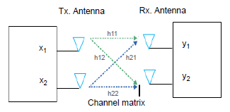
In this work, a 2 × 2 MIMO system with 𝐇𝐇 channel matrix is considered (Fig. 2). The relationship of input and output is expressed as
\( y(n)=\mathbf{H}(n) * \mathbf{X}(n)+\mathbf{N}_n(n) \) (30)
where 𝑦(𝑛) denotes the received signal, 𝐗(𝑛) is the transmitted signal, 𝐍𝑛(𝑛) as AWGN and 𝐇(𝑛) represent the N × M impulse response matrix, and (∗) corresponds to the convolution. The channel matrix 𝐇 explains the transmit and receive antennas in the propagation channel, which is given by
\( \mathbf{H}(\tau) \in \mathbf{C}^{N \times M} \Rightarrow \mathbf{H}=\left[\begin{array}{ll} h_{11} & h_{12} \\ h_{21} & h_{22} \end{array}\right] \) (31)
𝐇 denotes the complex matrix which depicts the linear transformation between two antennas at the delay τ. The transmission coefficient has the same average power 𝑃𝑖 and is assumed as zero mean complex Gaussian. The coefficients do not change depending on time delay. In reality, UWOC systems frequently uses large receiving apertures because background noise is so minimal in underwater. Additionally, though the attenuation caused by PE for free-space optics (FSO) links is modelled as random variable (RV) for simplicity, perfect alignment is first assumed since the marine optical channels are highly scattering in nature.
In order to model the turbulence-induced fading, let us assume that 𝛼=exp(𝑋) is the channel fading amplitude with a log-normal probability density function as [55]
\( f_\alpha(\alpha)=\frac{1}{\propto \sqrt{2 \pi \sigma_X^2}} \exp \left(\frac{-\left(\ln (\sigma)-\mu_X\right)^2}{2 \sigma_X^2}\right) \) (32)
The overall attenuation always disturbs the optical transmission especially in marine water. These coefficients were characterised as extinction coefficient which is given by 𝑐(𝜆)=𝑎(𝜆)+𝑏(𝜆). The 𝑏(𝜆) is the scattering coefficient which is obtained as
\( b=2 \pi \int \beta(\theta) \cdot \sin \theta d \theta \) (33)
where 𝛽(𝜃)denotes the volume scattering function (VSF), characterised by the portion of light intensity which diverges from an optical beam due to scattering. The Henyey-Greenstein function (HG), also known as scattering phase function is represented as [35]
\( P(\theta)=\frac{\left(1-g^2\right)}{4 \pi\left(1+g^2-2 g \cos \theta\right)^{3 / 2}} \) (34)
where 𝑔 stands for 𝐸cos𝜃 that means cosine of 𝜃 in all scattering directions. This work considered the UW channel link temporal response in coastal water and the value of water type is shown in Table 1 [38].
The initial divergence angle, the aperture size, the field of vision (FOV), and the link distance 𝐿 will all have a substantial impact on the impulse response of the systems [21]. According to Ref. 17, each photon is given four basic properties: weight, direction, position, and propagation time. The coordinates of the optical source to which the photons belong are used to initialise the Cartesian coordinate system (𝑥,𝑦,𝑧), which is used to represent the position. A spherical coordinate system zenith and azimuth angles are used to define each photon direction, which is originally only constrained by the divergence angle of the individual source [21].
Table 1.
Water properties-values for absorption coefficient, scattering coefficient and beam attenuation coefficient.
Water type |
a(λ) (m-1) |
b(λ) (m-1) |
c(λ)=a(λ)+b(λ) (m-1) |
Pure sea |
0.053 |
0.003 |
0.056 |
Coastal water |
0.179 |
0.219 |
0.398 |
Clear ocean |
0.114 |
0.037 |
0.151 |
Turbid water |
0.295 |
1.875 |
2.17 |
Each photon intensity is represented by the weight which starts at a value of 1. Path loss is calculated using a propagation time which is typically initialised as zero. The anticipated start time of the first photon is used to smooth the curve of channel impulse response [21]. These four characteristics of each photon will change during propaga-tion due to scattering and absorption. After interacting with the medium, a photon will transmit in steps size Δ𝑠, which is given as
\( \Delta s=\frac{\ln \varepsilon_\delta}{c} \) (35)
where 𝜀𝛿 is the random number with a uniform distribution between [0, 1]. The photon is lost due to attenuation when a photon interacts with a material. Due to this, weight of the photon is updated, which is represented by
\( W_{\text {post }}=W_{\text {pre }}(1-a / c) \) (36)
where 𝑊post and 𝑊pre are designated as the weights after and before interaction. Only photons arriving at the receiver that have positions inside the aperture weights higher than a predetermined threshold and arrival angles are acknowl-edged as detected photons [55].
Channel equalisation has become a key area in recent research into improving the performance of the system. Equalisation techniques adopted at the receiver can successfully reduce the impact of turbulence-induced fading, which in turn enhances the BER of the link. In this work, UWOC channel equalisation and estimation are evaluated with ZF, MMSE, and NLMS-DFE configuration. The system overall performance has always been influenced by various noises, including thermal noise, background light, shot noise, and dark current noise. The main noise components are characterised as equivalent noise components and they are independent of each other [56]. Additionally, it is assumed that the existence of ISI results in a poor bit-by-bit recognition. This detection approach estimates the channel state information (CSI) accessibility for threshold computation.
The proposed equalisation algorithms state that in order to assess the predicted signal x(n) from y(n), the received signal, an equalisation matrix 𝐖 must be formed as
\( \hat{x}(n)=\mathbf{W} * y(n) \) (37)
ZF equaliser is a linear-equalisation technique that performs the inverse of a channel frequency response [57]. A method for detecting matrix inversions is the ZF equaliser. The received vector must be subjected to the equalisation matrix 𝐖𝐖 in this procedure. The pseudo-inverse of channel matrix, denoted as 𝐖𝐖, is written as
\( \mathbf{W}_{\mathrm{ZF}}=\left(\mathbf{H}^{\mathrm{H}} \mathbf{H}\right)^{-1} \mathbf{H}^{\mathrm{H}} \) (38)
Another important linear equalisation method called MMSE is used to reduce the effects of noise and ISI. The estimate of the quadratic cost function is more closely related to the MMSE approach in Bayesian strategy. While the ZF receiver merely suppresses interference or noise, the MMSE receiver decreases both interference and noise components [57]. In this case, the equalisation matrix is given by
\( \mathbf{W}_{\text {MMSE }}=\left(\mathbf{H}^{\mathrm{H}} \mathbf{H}+N_0 \mathbf{I}\right)^{-1} H^H \) (39)
where 𝑁0 denotes the noise power and 𝐈𝐈 represents the identity matrix of transmitting and receiving antennas.
Another important and mostly used nonlinear equaliser is an adaptive DFE that frequently outperforms any linear equaliser to mitigate the effects of co-channel interference (CCI) and ISI in time-delayed environments, especially when the channel contains spectral nulls. The NLMS approach [58] is a type of adaptive algorithm used to train the parameters of such an adaptive decision feedback equaliser (ADFE). It selects a normalised step-size factor while taking into account the variation of the signal level at the filter output. This results in an algorithm that is reliable and converges quickly. The implementation of the NLMS algorithm for the DFE is explained below in detail. The input parameters used in the simulation are the impulse response 𝐻(𝑛), transmitted signal 𝑆(𝑛), upper bound for error Υ, received signal 𝑦(𝑛), 𝑆mn =max𝑛𝑆, and step-size control parameter 𝜛.
Implementation of the algorithm is given below:
\( \begin{aligned} & E_n<\Upsilon \| S_{M n}=0 \\ & W_{n+1}=W_n \end{aligned} \)
\( W_{n+1}=W_n+\frac{\omega}{S_{M n}}\left(E_n-\operatorname{sgn}\left(E_n\right) \Upsilon\right) * S(n) \) >
In the proposed work, the BER performance of a MIMO-based GFDM underwater optical communication system is simulated using the 2020 version of MATLAB. Table 2 provides a list of simulation parameters. The MC approach is used to simulate a 10 m optical link for 2 × 2 MIMO systems in order to explore how the coastal water affects channel loss, temporal dispersion, and channel spatial beam spreading. In this simulation, the result of the proposed system is analysed by considering different FEC coding techniques and equalisation methods. The proposed scheme uses a GFDM transceiver model through the UWOC channel by simulating the parameters of the coding and equalisation techniques to evaluate the BER.
Table 2.
Simulation parameters
Parameters |
Value |
No. of subcarriers |
128 |
Channel gain |
10 dB |
Roll-off pulse-shaping filter |
0.4 |
Data rate |
100 kbps |
Quantum efficiency |
0.8 |
Sample time |
0.01 s |
Power emitted by LASER |
0.1 W |
Half angle, FOV |
30° |
Receiver aperture diameter |
0.005 m |
Ambient optical power |
7 × 10⁻⁸ W |
Link span between Tx. and Rx. |
10 m |
Photodiode active area |
7.8 × 10⁻⁷ m2 |
Water refractive index |
1:331 |
Amplifier bandwidth |
4.5 × 10⁶ Hz |
Refractive index of water bottom surface |
1.45 |
Air refractive index |
1 |
Laser source wavelength |
532 nm |
Photon weight threshold |
106 |
In this work, the coded GFDM with equalisation techniques is proposed for the first time which provides a promising way to enhance the error performance of the UWOC system. Here, a 4-QAM mapping is used for the performance evaluation. If the order of the QAM is increased, further improvement and better results can be achieved. Fig. 3 illustrates the 4-QAM constellation diagram of ZF, MMSE, and NLMS receiver. It can be seen that there is a remarkable improvement for NLMS technique.

Fig. 4 to 6 represent the BER waveform of uncoded and RS coded system with ZF, MMSE, and NLMS for different values of SNR. When SNR increases, the BER value is reduced. While comparing BER performance of the coded and uncoded system, there is a vast variation between them. Here, different coding schemes have been used: RS (15, 7), RS (15, 5), RS (15, 3).
Only RS (15, 3) has a reduced BER performance compared with other schemes for all the equaliser types. Only NLMS technique outperforms the other equaliser techniques and for RS (15, 3) scheme, BER of 1.1925 × 10⁻⁵ is achieved at 10 dB itself.

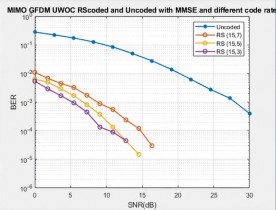
It is inferred from Fig. 6 that RS coded scheme has achieved a BER value of 1.19 × 10⁻⁵ at 11 dB, which is 16 dB less than uncoded system. For MMSE scheme (Fig. 5), it is around 3.9 × 10⁻⁵ at 12 dB, and for ZF method (Fig. 4), BER of 1.43 × 10⁻⁵ at 18 dB is achieved.
Also, it can be seen from the Fig. 4 that for ZF equaliser, RS (15, 3), RS (15, 5), and RS (15, 7) achieved the FEC limit at 10 dB, 11 dB, 15 dB, respectively at a BER of 10−3 , while the uncoded system achieved only at 27 dB.
p > In the case of the MMSE equaliser (Fig. 5), RS (15, 3), RS (15, 5), and RS (15, 7) achieved the FEC limit at 5 dB, 7 dB, 9 dB, respectively at a BER of 10−3 and the uncoded system achieved only at 28 dB. 
Similarly for the NLMS equaliser (Fig. 6), RS (15, 3), RS (15, 5), and RS (15, 7) achieved the FEC limit at 3 dB, 4 dB, 6 dB, respectively and the uncoded system achieved only at 22 dB.
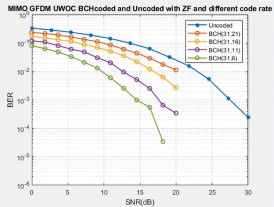
Fig. 7 to 9 represent the BER performance of BCH coded scheme with ZF, MMSE, and NLMS equalisation for different values of SNR. Here, different coding schemes of BCH (31, 21), BCH (31, 16), BCH (31, 11), BCH (31, 6) were considered for evaluation. From the inference of the above said figure, BCH (31, 6) scheme proves to be more efficient than other schemes used in this work.
The uncoded GFDM system achieved the minimum BER value of 3.78 × 10⁻⁵ only at 30 dB. With BCH (31, 6) coded scheme, only NLMS equalisation method achieved a BER of 1.08 × 10⁻⁴ at 9 dB itself. This results in 18 dB less than the uncoded system.
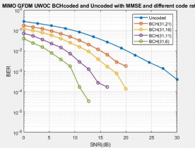
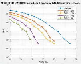
While comparing BCH and RS coding schemes with different equalisation methods, only RS coded system is efficient and has promising results with less error rate by reconstructing the quality of the original signal. Also, it can be seen that BCH (31, 6) has achieved the FEC limit (⁓ 10−3 ) at 15 dB for ZF equaliser, at 9 dB for MMSE, and 7 dB for NLMS equaliser.
The BER performance of the uncoded and coded GFDM-based UWOC system is analysed under weak and strong turbulence conditions in underwater link for different equalisation techniques. The refractive index structural parameter 𝐶 𝑛2 represents the degree of turbulence in the propagating medium. More frequently, strong and weak channel turbulence conditions are related with the numerical values of 𝐶 𝑛2 as 10-13 m-2/3m−2/3, respe-2/3only RS (15, 3) and BCH (31, 6) coded schemes are considered for evaluation based on the inference from the previous figure.
Fig. 10 to 12 represent the BER performance of the coded and uncoded GFDM system under weak turbulence condition (𝐶 𝑛2= 10−17 m-2/3rent equalisations methods. From the beneath figure, it is apparent that RS coded scheme is more efficient than BCH code and achieved a BER value of 5.56 × 10⁻⁵ at 7 dB for NLMS method, 1.65 × 10⁻⁵ at 9 dB for MMSE method, and 2.92 × 10⁻⁵ at 12 dB for ZF method.

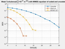

Fig. 13 to 15 represent the BER performance of the coded and uncoded GFDM system under strong turbulence condition (𝐶n 2= 10-13 m-2/3rent equalisations methods. From the beneath figures, it can be seen that RS coded scheme achieves a BER value of 5.74 ×10⁻⁵ at 8 dB for NLMS method, 1.37 × 10⁻⁵ at 12 dB for MMSE method, and 1.38 × 10⁻⁵ at 16 dB for ZF method. RS coded scheme has accomplished BER value less than 6 dB and 15 dB SNR for BCH and uncoded schemes, respectively.

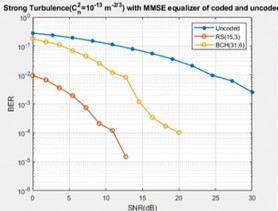
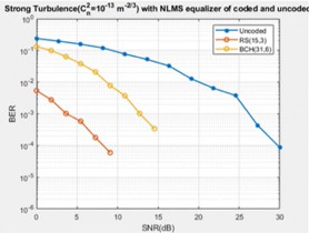
Fig. 16 to 18 represent the BER performance with PE (𝜎𝑃 =2) and weak turbulence (𝐶n 2= 10−17 m 2/3) to illustrate the comparison of the uncoded GFDM with the RS and BCH coded GFDM scheme for different equalisations. It can be seen from the figures that RS coded system achieves a BER of 7.75 × 10⁻⁴ for ZF receiver, 4.95 × 10⁻⁵ for MMSE receiver, and 1.54 × 10⁻⁵ for NLMS receiver at 7 dB SNR value. In the case of BCH coded system, a BER value of 4.89 × 10⁻², 1.07 × 10⁻² and 2.42 × 10⁻³ has been attained for ZF, MMSE, and NLMS receiver, for the same SNR value, respectively. It is inferred that the RS is most efficient by comparing the selected BCH and RS encoding schemes, i.e., BCH (31, 6), RS (15, 3).
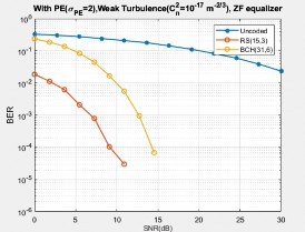

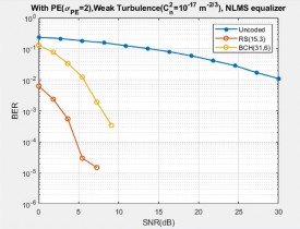
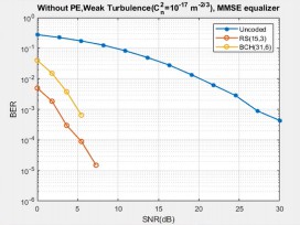
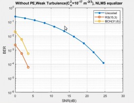
Fig. 19 to 21 represent the performance in the presence of weak turbulence (𝐶 𝑛2 = 10−17 m-2/3ut PE condition for different equalisations. It shows that for NLMS technique, RS (15, 3) coded system achieves less BER of 5.92 × 10⁻⁵ at 3 dB SNR itself, when compared to other equalisation techniques. It is approximately 27 dB less than the uncoded system. For the same SNR value, BCH (31, 6) coded system achieved BER value of 6.38 × 10⁻⁴. It can be inferred that the RS coded scheme with the NLMS algorithm effectively improves the BER performance by exploiting the advantages of error correcting capability.

In this paper, the performance of the coded GFDM-based UWOC system is analysed by using different equaliser techniques over an UW channel. Also, the BER performance of the system under weak and strong oceanic turbulence in the presence and absence of PE was evaluated. Simulation results demonstrated that, among other coding schemes, RS (15, 3) and BCH (31, 6) provided a better error performance. From the observation and simulation results, RS (15, 3)-coded 2 × 2 MIMO systems with NLMS-DFE achieved a BER value of 1.1925 × 10⁻⁵ at 11 dB which is 16 dB less than the uncoded system. The findings indicated that the error control coding technique might be a practical way to enhance the wireless optical communication dependability in an unstable oceanographic environment. Therefore, it is concluded that the use of diversity schemes along with a suitable channel coding technique will be effective for a reliable high-speed communication in UWOC systems. Also, the results proved that the coded GFDM with NLMS-DFE equalisation is better than other equaliser techniques and significantly improves the overall perfor-mance in coastal water conditions and enables IoUT applications such as underwater communication between underwater vehicles and objects, submarine communication, as well as collecting oceanographic parameters, etc.
The authors would like to wholeheartedly extend their thanks for providing lab facilities and faculty of Easwari Engineering College for the useful discussions and mentoring.
Sozer, E. M., Stojanovic, M. & Proakis, J. G. Underwater acoustic networks. IEEE J. Ocean. Eng. 25, 72–83 (2000). https://doi.org/10.1109/48.820738
Stojanovic, M. Recent advances in high-speed underwater acoustic communications. IEEE J. Ocean. Eng. 21, 125–136 (1996). https://doi.org/10.1109/48.486787
BlueComm 200, underwater optical communications and data transfer modem. Sonardyne Int. Ltd.https://www.sonardyne.com/products/bluecomm-200-wireless-underwater-link/
Che, X. H., Wells, I., Dickers, G., Kear, P. & Gong, X. C. Re- evaluation of RF electromagnetic communication in underwater sensor networks. IEEE Commun. Mag. 48, 143–151 (2011). https://doi.org/10.1109/MCOM.2010.5673085
Giuseppe S S, Cozzella L. & Leccese F. Underwater optical wireless communication: overview. Sensors 20, 2261 (2020). https://doi.org/10.3390/s20082261
Zeng, Z., Fu, S., Zhang, H., Dong, Y. & Cheng, J. A survey of under- water optical wireless communications. IEEE Commun. Surv. Tutor. 19, 1, 204–238 (2017). https://doi.org/10.1109/COMST.2016.2618841
Sun, X. et al. A review on practical considerations and solutions in underwater wireless optical communication. J. Light. Technol. 38, 421–431 (2020). https://doi.org/10.1109/JLT.2019.2960131
Jurado-Navas, A., Serrato, N. G, Garrido-Balsells, J. & Castillo- Vázquez, M. Error probability analysis of OOK and variable weight MPPM coding schemes for underwater optical communication systems affected by salinity turbulence. OSA Continuum 1, 1131– 1143 (2018). https://doi.org/10.1364/OSAC.1.001131
Schirripa Spagnolo, G., Cozzella, L. & Leccese, F. Underwater optical wireless communications: Overview. Sensors (Basel) 20, 2261 (2020). https://doi.org/10.3390/s20082261
Leccese, F. & Schirripa Spagnolo, G. State-of-the art and perspec- tives of underwater optical wireless communications. Acta IMEKO 10, 25–35 (2021). https://doi.org/10.21014/acta_imeko.v10i4.1097
Mobley, C. D. Light and Water: Radiative Transfer in Natural Waters. (Academic Press, New York, NY, 1994)
Domingo, M. C. An overview of the Internet of underwater things.J. Netw. Comput. Appl. 35, 1879–1890 (2012). https://doi.org/10.1016/j.jnca.2012.07.012
Zedini, E. et al. Performance analysis of dual-hop underwater wireless optical communication systems over mixture exponential- generalized gamma turbulence channels. IEEE Trans. Commun. 68, 5718–5731 (2020). http://dx.doi.org/10.1109/TCOMM.2020.3006146"
Mobley, C. D. et al. Comparison of numerical model for computing underwater light fields. Appl. Opt. 32, 7484–7504 (1993). https://doi.org/10.1364/AO.32.007484
Hema, R., Sudha, S. & Aarthi, K. Performance studies of MIMO based DCO OFDM in underwater wireless optical communication systems. J. Mar. Sci. Technol. 26, 97–107 (2021). http://dx.doi.org/10.1007/s00773-020-00724-7
Ahmad, Z. et.al. Performance of spatial diversity DCO-OFDM in a weak turbulence underwater visible light communication channel. J. Light. Technol. 38, 2271–2277 (2020). http://dx.doi.org/10.1109/JLT.2019.2963752
Zedini, E. et al. Unified statistical channel model for turbulence induced fading in underwater wireless optical communication systems. IEEE Trans. Commun. 67, 2893–2907 (2019). https://doi.org/10.1109/TCOMM.2019.2891542
Rahman, Z., Bansal, A. & Zafaruddin, S. M. Diversity analysis of multi-aperture UWOC system over EGG channel with pointing errors. IEEE Commun. Lett. 27, 2073–2077 (2023). https://doi.org/10.1109/LCOMM.2023.3281613
Ali, M. A. A. Characteristics of optical channel for underwater optical wireless communication system. IOSR J. Electr. Electron. Eng. 10, 01–09 (2015). https://doi.org/10.9790/1676-10210109
Jamali, M. V. et al. Statistical studies of fading in underwater wireless optical channels in the presence of air bubble, temperature, and salinity random variations. IEEE Trans. Commun. 66, 4706– 4723 (2018). https://doi.org/10.1109/TCOMM.2018.2842212
Gussen, C. M. et al. A survey of underwater wireless communi- cation technologies. J. Commun. Inf. Sys. 31, 242–255 (2016). https://doi.org/10.14209/jcis.2016.22
Majlesein, B., Gholami, A. & Ghassemlooy, Z. A Complete Model for Underwater Optical Wireless Communications System. in 11th Int. Symp. Commun. Syst. Networks Digit. Signal Process (CSNDSP) 1–5 (IEEE, 2018). https://doi.org/10.1109/CSNDSP.2018.8471869
Jamali, M. V., Salehi, J. A. & Akhoundi, F. Performance studies of underwater wireless optical communication systems with spatial diversity: MIMO scheme. IEEE Trans Commun. 65, 1176–1192 (2017). https://doi.org/10.1109/TCOMM.2016.2642943
Chen, W. et al. Impact of temperature gradients on average bit error rate performance of low-density parity-check-coded multihop underwater wireless optical communication systems over the generalized gamma distribution. Proc. SPIE 59, 016114 (2020). https://doi.org/10.1117/1.OE.59.1.016114
Geldard, C. T., Thompson, J. & Popoola, W O. Empirical study of the underwater turbulence effect on non-coherent. IEEE Photon. Technol. Lett. 32, 1307–1310 (2020). https://doi.org/10.1109/LPT.2020.3020368
Baykal, Y, Ata, Y. & Gökçe, M.C. Underwater turbulence, its effects on optical wireless communication and imaging: A review. Opt. Laser Technol. 156, 108624 (2022). https://doi.org/10.1016/j.optlastec.2022.108624
Yılmaz A, Elamassie M, Uysal M. Diversity Gain Analysis of Underwater Vertical MIMO VLC Links in the Presence of Turbulence. in 7th IEEE International Black Sea Conference on Communications and Networking 1–6 (IEEE, 2019). https://doi.org/10.1109/BlackSeaCom.2019.8812823
Baykal, Y., Gökçe, M. C. & Ata, Y. Anisotropy effect on performance of subcarrier intensity modulated binary phase shift keying optical wireless communication links in weakly turbulent UW channel. J. Mod. Opt. 66,1871–1875 (2019). https://doi.org/10.1080/09500340.2019.1682208
He, F. Bit error rate of pulse position modulation wireless optical communication in gamma-gamma oceanic anisotropic turbulence. Acta Phys. Sin-Ch. Ed. 68, 164206 (2019). https://doi.org/10.7498/aps.68.20190452(in Chinese)
Mattoussi, F., Khalighi, M. A. & Bourennane, S. Improving perfor- mance of underwater wireless optical communication links by channel coding. Appl. Opt. 57, 2115–2120 (2018). https://doi.org/10.1364/AO.57.002115
Cox, W. C, Simpson, J. A., Domizioli, C. P., Muth, J. F. & Hughes, B. L. An Underwater Optical Communication System Implementing Reed–Solomon Channel Coding. in OCEANS 1–6 (IEEE, 2008). https://doi.org/10.1109/OCEANS.2008.5151992
Xu, J. et al. OFDM-based broadband underwater wireless optical communication system using a compact blue LED. Opt. Commun. 369, 100–105 (2016). https://doi.org/10.1016/j.optcom.2016.02.044
Huang, A., Tao, L. & Jiang, Q. BER Performance of Underwater Optical Wireless MIMO Communications With Spatial Modulation Under Weak Turbulence. in OCEANS-MTS 1–15 (IEEE, 2018). https://doi.org/10.1109/OCEANSKOBE.2018.8559096
Amantayeva, A., Yerzhanova, M. & Kizilirmak, R. C. Multiuser MIMO for Underwater Visible Light Communication. in 2018 International Conference on Computing and Network Communications (CoCoNet) 164–168 (IEEE, 2018). https://doi.org/10.1109/CoCoNet.2018.8476887
Nissel, R., Schwartz, S. & Rupp, M. Filter bank multicarrier modulation schemes for future mobile communications. IEEE J. Sel. 35, 1768–1782 (2018). https://doi.org/10.1109/JSAC.2017.2710022
Rajappa, A. C. J. et al. Golden coded GFDM for 5G communication. Wirel. Pers. Commun. 115, 2335–2348 (2020). https://doi.org/10.1007/s11277-020-07684-6
Kaushal, H. & Kaddoum, G. Underwater optical wireless communication. IEEE Access. 4, 1518–1547 (2016). https://doi.org/10.1109/ACCESS.2016.2552538
Ramadan, K. & Elbakry, M. Efficient equalization and carrier frequency offset compensation for underwater wireless communication systems. Ann. Data Sci. 9, 1–21 (2022). https://doi.org/10.1007/s40745-022-00449-x
Chao, F. et al. Underwater wireless optical communication utilizing low-complexity sparse pruned-term-based nonlinear decision- feedback equalization. Appl. Opt. 61, 6534–6543 (2022). https://doi.org/10.1364/AO.462827
Krishnamoorthy, R. N., Rajkumar, I., Alexander, J. & Devaerakkam, M. Impact of equalizer step size in underwater acoustic communication channel. Int. J. Comput. Netw. Secur. 13, 29–38 (2021). https://doi.org/10.5815/ijcnis.2021.01.03
Zhang, J. et al. Monte-Carlo-based optical wireless UW channel modeling with oceanic turbulence. Opt. Commun. 475, 126214 (2020). https://doi.org/10.1016/j.optcom.2020.126214
Kumar, K., Jha, P. & Shukla, S. Monte Carlo simulation of BER performance of underwater optical link over log normal fading channel. Int. J. Emerg. Technol. Innov. Eng. 5, 722–725 (2019). https://ssrn.com/abstract=3450134
Murad, M., Tasadduq, I. A. & Otero, P. Coded-GFDM for reliable communication in underwater acoustic channels. Sensors 22, 2639 (2022). https://doi.org/10.3390/s22072639
Michailow, N. et al. Generalized frequency division multiplexing for 5th generation cellular networks. IEEE Trans. Commun. 62, 3045–3061 (2014). https://doi.org/10.1109/TCOMM.2014.2345566
Farhang, A., Marchetti, N. & Doyle, L. Low complexity transceiver design for GFDM. IEEE Trans. Signal Process. 64, 1507–1518 (2016). https://doi.org/10.1109/TSP.2015.2502546
Ramavath, P. N., Kumar, A., Godkhindi, S. S. & Acharya, U. S. Experimental studies on the performance of underwater optical com- munication link with channel coding and interleaving. CSI Trans.ICT 6, 65–70, (2018). https://doi.org/10.1007/s40012-017-0179-3
Farid, A. A. & Hranilovic, S. Outage Probability for Free-Space Optical Systems Over Slow Fading Channels With Pointing Errors. in LEOS 19th Annual Meeting of the IEEE Lasers and Electro- Optics Society 82–83 (IEEE, 2006). https://doi.org/10.1109/LEOS.2006.278847
Yu, X., Jin, W., Sui, M. & Lan, Z. Evaluation of Forward Error Correction Scheme for Underwater Wireless Optical Communication. in 2011 IEEE, Third International Conference on Communications and Mobile Computing 527–530 (IEEE, 2011). https://doi.org/10.1109/CMC.2011.49
Labrador, Y., Karimi, M., Pan, D. & Miller, J. Modulation and error correction in the underwater acoustic communication channel. Int. J. Comput. Sci. Netw. Secur. 9, 123–130 (2009). http://paper.ijcsns.org/07_book/200907/20090718.pdf
Lin S, Costello Jr., D. J. Error Control Coding. (Prentice Hall: Pearson Education India; 2001).
Moon, T. K. Error Correction Coding: Mathematical Methods and Algorithms. (John Wiley & Sons, 2005). https://doi.org/10.1002/0471739219
Ramavath, P. N, Udupi, S, A, & Krishnan, P. High-speed and reliable underwater wireless optical communication system using multiple-input multiple-output and channel coding techniques for iout applications. Opt. Commun. 461, 125229 (2020). https://doi.org/10.1016/j.optcom.2019.125229
Mahapatra, S. K & Varshney, S, K. Performance of the Reed- Solomon-coded underwater optical wireless communication system with orientation-based solar light noise. J. Opt. Soc. Am. 39, 1236– 1245 (2022). https://doi.org/10.1364/JOSAA.453257
Safari, M. & Uysal, M. Relay-assisted free-space optical commu- nication. IEEE Trans.Wireless Commun. 7, 5441–5449 (2008). https://doi.org/10.1109/T-WC.2008.071352
Manimegalai, C. T., Bhatta, H., Thakur, H. & Iliyas, A. Channel modeling for UWOC: a simulation approach. J. Opt. 51, 810–818 (2022). https://doi.org/10.1007/s12596-022-00854-8
Mahanta, S. & Rajauria, A. Analysis of MIMO System through ZF & MMSE Detection Scheme. Int. J. Electron. Commun. Technol. 4, 84–87 (2013). https://iject.org/vol4/spl4/c0142.pdf
Mitra, A. An efficient decision feedback equalizer with a novel block based NLMS algorithm. IETE J. Res. 54, 61–69 (2014). https://doi.org/10.1080/03772063.2008.10876183